In my first two blogs on this topic I talked about why DSPs are suddenly popping up everywhere and why particularly they are starting to displace some custom hardware accelerators (HWA) as a more flexible and future-proofed option. In this blog I want to talk about a more detailed analysis you can follow to decide if you should be thinking about a DSP rather than an HWA implementation.

(Source: CEVA)
I mentioned in the last blog some of the ideal applications for DSPs. Signal processing for modem or audio signals are obvious examples. Another very common example is the signal processing in radars for autonomous cars, which is quite similar to the signal processing in a modem. Many of these have been built around a hardware accelerator combined with a small controller. We’re now seeing a significant trend among those solution-providers to switch to architectures in which more of the functionality is based on software running on a DSP, combining the signal processing currently handled by the HWA and even some control. The reasoning is simple: Software provides more flexibility in functionality and much lower-cost and more timely ability to adapt to evolving communication standards.
Global positioning is another application, in this case heavily leveraging the math capabilities inherent to DSPs for the triangulation calculations. You might initially think that GPS support is all you need and perhaps you can build a really fast implementation in a hardware accelerator. However in the global GNSS standard you also need to consider support for GLONASS (Russia), Galileo (Europe) and BeiDou (China). A hardwired implementation for GPS may limit your markets unnecessarily since supporting all variants can be accomplished in software if you’re running on a DSP.
So far, so good in principle, but how will a DSP implementation perform versus a custom hardware implementation? I’ll illustrate with one popular example today: Say you’re building an IoT application and you plan to use NB-IoT for communication. The sub frame length is 1ms which defines a bounding limit for certain processing that must be completed within that time. In this example, that would include the physical layer algorithms, the L1 control code and the protocol stack. For a typical low-power DSP/NB-IoT platform running at 100MHz, 1ms gives you 100k cycles in which to complete those calculations.
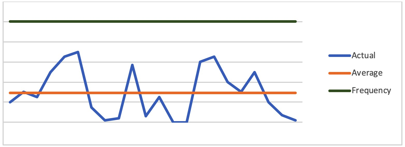
To estimate what kind of performance you can expect in an equivalent DSP implementation, you’ll need to work with an embedded DSP vendor. Such a company should already offer software solutions on their platforms for multiple applications, which they will have characterized for performance and power. For performance they should be able to give you a cycle-count estimate for your function, in this case an NB-IoT modem, and provide you with a graph, similar to the one below. Each point in the graph represents the number of cycles required to execute and the graph is charted across a time-varying range of loads. The graph should also show peak-allowable cycles given a selected operating frequency.

(Source: CEVA)
Now you have a method to estimate whether your application load will work at that frequency, or whether you might need to increase the frequency to give you more headroom. Of course this estimate is based on the vendor’s software implementation, though it’s reasonable to expect it will be pretty well tuned. You don’t have to commit to using their software, but the estimate should be good enough to guide your decision-making.
If you have plenty of headroom at your preferred operating frequency, perhaps you can move more HWA functions onto the DSP, or maybe add more differentiating features such as GNSS location support. If on the other hand you need to increase the frequency to meet latency requirements, that is also possible though you should factor in that bumping up the frequency will increase area and power consumption.
A quick way to get an estimate of power is to look at how much of the software is going to go into true DSP code, using parallelism, MAC units etc., and how much is going to go into control code – the usual general-purpose code calling functions, making decisions and other standard operations. You can usually eyeball this split, say 40% control code and 60% DSP code. A DSP vendor will often provide typical power numbers for these two cases, for example 2mW for control code and 4mW for DSP code (in each case at 100MHz). In your calculation you should factor in the average activity of the DSP, for example 50% of the frequency. So in this example you would estimate (0.4*2 + 0.6*4) * 0.5 = 1.6 mW average power (assuming 50% average activity).
In summary, you should be able to develop a pretty reasonable estimate of what performance and power you can expect for a DSP implementation of your accelerator function (unless you’re developing something really unusual – in this case you should model your application in the DSP’s SW tools to get a pretty accurate estimation for the cycle count). When you consider the added flexibility you get from a software implementation and the ability to save cost by combining multiple accelerators onto one processor, a DSP solution looks pretty attractive.
Published on Embedded.com.

