A gyroscope senses change in orientation of a device, and when paired with an accelerometer, is an excellent tool for measuring the orientation of an object in 3D space.
Thursday, November 29, 2018
In an earlier post, we defined a piece of technology that is helping to shape the future—the IMU sensor. Today, we are going to take a deeper look at one motion sensor in particular, the gyroscope.
A gyroscope senses change in orientation of a device, and when paired with an accelerometer, is an excellent tool for measuring the orientation of an object in 3D space. Gyroscopes determine angular velocity (ω) typically measured in radians/second. The integration of angular velocity provides orientation information (if an initial orientation is provided or a value can be assumed) across three axes: pitch, roll and yaw.
A gyroscope enables tracking of the twists, turns and rolls of an object in motion. Access to more accurate orientation information has wide-ranging practical applications, for instance, helping a land based robot account for obstacles it runs over, translating a person’s real world movement into a virtual world, or helping to orient an aircraft in flight.
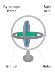
A traditional, mechanical gyroscope is a simple wheel that’s mounted on 2-3 gimbals (pivoted supports, typically rings, that let the wheel rotate on a single axis.) Gyroscopes were first used in the mid-19th century for early renderings of the earth’s orbit and have since been used in the inertial navigation systems of aircrafts, ships, spacecrafts and satellites. However, despite its ubiquitous use, the traditional mechanical gyroscope is limited to its moving parts.
Let’s explore modern gyroscope types and their applications:

Ring Laser Gyroscope (RLG)
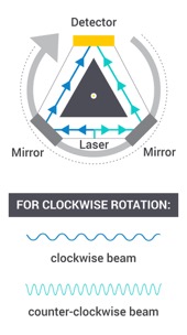
Ring Laser Gyroscopes operate on the Sagnac Effect, which in short says that a split beam of light traveling the same path in opposite directions will undergo phase changes when the whole apparatus experiences angular velocity. In the diagram shown, a laser is split into two along two paths of equal length and are received at a detector. As the RLG rotates clockwise, the beam moving clockwise effectively travels a slightly longer path and slowing down its reception by the detector. The counterclockwise beam is traveling against the rotation, effectively shortening the path, increasing its speed relative to the other laser. The opposite effect occurs under a counterclockwise rotation.
By measuring the phase changes while the device is rotating, angular velocity can be ascertained.
Uses:
- Inertial navigation systems in military aircraft, commercial airliners, ships and spacecrafts
Pros:
- High performance:
- High accuracy, better than 0.01°/hour bias uncertainty
- MTBF (mean time between failures) greater than 60k hours
- No mechanical or moving parts to create friction, so there is no drift
Cons:
- At very slow rotations, the counter-operating frequencies can become so similar as to be indistinguishable, resulting in the beams “locking” to one another rather than the rotation; this is referred to as lock-in
- Can only be used for a single axis, to get multiple-axis information, multiple RLGs are needed

Fiber Optic Gyroscope (FOG)
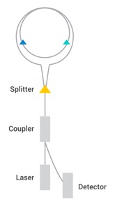
FOGs also use the Sagnac effect, but compounds the effect multiple times by using multiple coils for the light to travel (as opposed to a single ring like with the RLG). Additionally, the rings are not part of the laser. Instead, the light beams are propagated by an external laser. Once again, the light beam propagating in the same direction as the rotation will have a somewhat longer path delay than the beam that’s running against the rotation. This results in a differential phase shift, measured with interferometry.
The differential phase shift is effectively multiplied by each additional coil that the FOG uses. This multiplication allows the FOG to have an increased sensitivity in general over the RLG. However, with a single traversal of light through the ring, a RLG is more accurate as its phase shift is proportional to the rotation itself, and not the derivative, like a FOG would have to use.
Uses:
- High-shock applications such as gun pointing systems (however, they often need to be paired with multiple-axis FOG and accelerometers to overcome their sensitivity to vibrations)
- High-performance space applications
- Fiber optic gyrocompasses for navigation systems
- Inertial navigation systems of guided missiles
- Remotely-operated vehicles and autonomous underwater vehicles
- Surveying equipment
Pros:
- Extremely precise rotational rate information
- No moving parts
- Doesn’t rely on inertial resistance to movement
- Typically shows higher resolution than RLG
Cons:
- Longer production times due to higher calibration requirements
- Can only be used for a single axis, to get multiple-axis information, multiple FOGs are needed

MEMS-Based Gyroscope (MEMS)
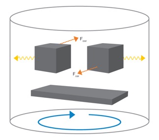
MEMS (microelectromechanical systems) use a combination of mechanical oscillation and Coriolis force. The Coriolis force is the inertial force that acts in a direction perpendicular to the rotation axis. Inside the MEMS gyro, imagine a capacitive block that oscillates at a fixed rate in opposite phase with another block. As the device rotates, the blocks’ Coriolis forces move them slightly in opposite directions (both perpendicular to the rotation axis), due to the blocks’ phase differences. This difference in force changes the capacitance of the plate underneath it to measure the overall angular rate of an object. In reality, the blocks are more like meshes, but the same basic principle applies.
MEMS gyroscopes are typically 3-axis, but can be single axis or dual axis. Different levels of quality are also available, depending on application requirements. For instance, consumer grade gyros tend to be cheaper than ones intended for industrial or automotive use, which operate at wider temperature ranges and are designed and tested to have more consistent performance in order to meet stringent safety requirements.
Uses:
- “Smart” technologies in homes, cities and cars
- IMUs (when coupled with an accelerometer and magnetometer)
- Industrial and automotive applications, such as GPS systems (higher-cost MEMS)
- Portable consumer electronics such as tablets, smartphones, smartwatches, game controllers, AR/VR headsets and robotic cleaners (lower-cost MEMS)
- Optical image stabilization in cameras
- Mobile and VR gaming applications
Pros:
- Significantly smaller form factor than other gyroscopes
- Can be integrated with a digital interface in a single cost-effective package
- Lower power
- Significantly lower cost than FOG or RLG and therefore able to be used in mass market consumer products
Cons:
- Less stability over temperature, humidity and stress, some of which can be compensated for with software
- More integration error relative to FOG or RLG
- Often varied performance across lots and units

Modern RLG, FOG, and MEMS-based gyroscopes all address limitations of traditional gyroscopes. And with their varied strengths, they are able to support next-gen technologies in all fields.
In the consumer space in particular, MEMS-based gyroscopes are growing in popularity and adding functionality to a lot of consumer devices, due to their ease of integration, size, and cost.

